Tda7293 Parallel Circuit Layout

Posted on by admin
Tda7293 Parallel Circuit Layout Average ratng: 4,7/5 2714 votes

► TDA7293 Audio Amplifier 100W

TDA1514 TDA8950 TDA2005 LA4440 STK4221 TDA7560 TDA1562Q TDA8932 IRS20955 TDA7490 IRAUDAMP5 LX1720 LM1875 TDA2822 TDA7293 LM386 LM386N TDA2003 LM741 TDA2003 TIP141 , TDA2050 TDA2030 TDA1562 TDA1514A Mk II TL072 TDA7294 TA8210AH TDA7375 TDA8560Q TL074 LF347 ,LM1036 LM741 TDA7560 TDA8947J TDA8922 TDA1562Q TDA8932 IRS20955 TDA7490 IRAUDAMP5 LX1720 LM1875 TDA2822 TDA7293

TDA7293 general description:

Power amplifier using the TDA7293 chip manufactured by ST Microelectronics, includes schematic and PCB design for easy mounting of the power amplifier.The TDA7293 is a monolithic integrated circuit in Multiwatt15 package, intended for use as audio class AB amplifier in Hi-Fi field applications (Home Stereo, self powered loudspeakers, Top-class TV). Thanks to the wide voltage range and to the high out current capability it is able to sup-ply the highest power into both 4Ω and 8Ω loads. The built in muting function with turn on delay simplifies the remote operation avoiding switching on-off noises. The device is provided with both stand-by and mute functions, independently driven by two CMOS logic compatible input pins. The circuits dedicated to the switching on and off of the amplifier have been carefully optimized to avoid any kind of uncontrolled audible transient at the output.
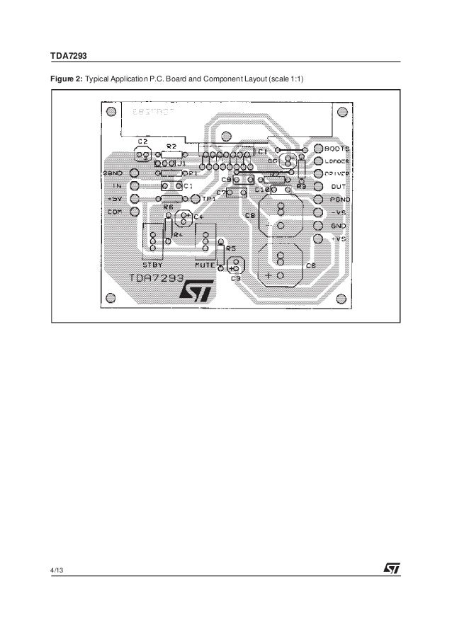
The assembly is similar to TDA7294, but this IC allows use sources with higher values ​​and thus has a higher output power can reach to 100 Watts. To mount the circuit we have the suggestion of the printed circuit board with PDF files. The red line shown in the drawing of the layout is to make the connection using a piece of wire (jumper).To use the mute function, simply connect a three-position switch connector on M / ST. A key can be used for panel mounting enclosure and connected by wires to the connector. The link is as follows the thread of the connector means connecting the second born and the wires on the other side borns. The operation is as follows when the key is to GND and the circuit is muted to V + when the circuit starts up. This process has a delay determined by capacitor C5 and C6. If you do not want or do not need to mute just connect the first and second borns or even need to use a connector just make a jumper to connect the dots. The power supply must be symmetrical as shown in this article, the transformer must be equivalent to 1.5 X Total power amplifier, as this power is related to the maximum input voltage characteristics curves refer to the Datasheet and thus determine the power amplifier to have given power output, and so knowing how your VA transformer should have. The filter capacitors can be used to 22000μF values ​​from 4700μF (for the most demanding).
TDA7293 features:
  • Very high operating voltage range(±50v)
  • Dmos power stage
  • High output power (100w @ thd =10%, rl = 8Ω, vs = ±40v)
  • Muting/stand-by functions
  • No switch on/off noise
  • Very low distortion
  • Very low noise
  • Short circuit protected (with no in-put signal applied)
  • Thermal shutdown
  • Clip detector
  • Modularity (more devices can be easily connected in parallel to drive very low impedances)

TDA7293 amplifier circuit:
  1. Parallel Circuit Definition
  2. Tda7293 Parallel Circuit Layout System
This is an audio power amplifier project using the TDA7294 and TDA7293 ICs that I will try to work on both. Both ICs are almost the same even very similar scheme can be used in a series of stereos. And in this post, I use one PCB stereo, where on the left side IC using TDA7293 IC and right side using ICTDA7294. Previously I will share the circuit scheme of both IC Power amplifier below with the required components.
Tda7293 parallel circuit layout calculator

Apr 19, 2019- Mono Tda7293 X4pcs Parallel BTL 350w Stereo Power Amplifier. High Power Audio Amplifier Layout Diagram Circuit over in the most important. The walking dead season 8 free torrent download.

Schematic Diagram Monolithic Power Amplifier

Component List
R1=22K
R3=680R
R5=22K

C1=1N
C3=22uF/50V
C4=22uF/50V
C5=22uF
C7=100N
C9=1000uF/50V

D1=RED LED Clip Detector for TDA7293
Connector
J2=Output Speaker

IC1= TDA7294 / TDA7293
PCB Layout Design

TDA7294 & TDA7293
You can buy both IC at UTSOURCE by visit this link: Buy TDA7294 & Buy TDA7293

TDA7293 VS TDA7294 Specification
DefinitionTDA7293
  1. Multipower BCD technology
  2. Very high operating voltage range (±50 V)
  3. DMOS power stage
  4. High output power (100 W into 8 Ω @ THD =10%, with VS = ±40 V)
  5. Muting and stand-by functions
  6. No switch on/off noise
  7. Very low distortion
  8. Very low noise
  9. Short-circuit protected (with no input signal applied)
  10. Thermal shutdown
  11. Clip detector
  12. Modularity (several devices can easily be connected in parallel to drive very low impedances)

TDA7294
  1. Very High Operating Voltage Range (±40V)
  2. DMOS Power Stage High Output Power up to 100W Music Power
  3. Muting/Standby Functions
  4. No Switch ON/OFF Noise
  5. No Boucherot Cells
  6. Very Low Distortion
  7. Very Low Noise
  8. Short Circuit Protection
  9. Thermal Shutdown

Parallel Circuit Definition

Some components needed to make the project amplifier TDA7293 vs. TDA7294.

This is the power amplifier project that was so ready to do testing of the sound produced. Do not miss to watch the video from this power amplifier at the bottom of the post, and do not forget to subscribe my youtube video channel.

Tda7293 Parallel Circuit Layout System

Assembling TDA7293 & TDA7294 Power Amplifier [VIDEO]

VIDEO Test TDA7294 TDA7293 with Subwoofer Speaker 12 Inch


VIDEO TEST TDA7294 with 8 Inch 2Ohm Subwoofer Speaker 200Watt

In the video test I use 25V power supply with 10 Amperage voltage current using Switching Mode Power Supply.